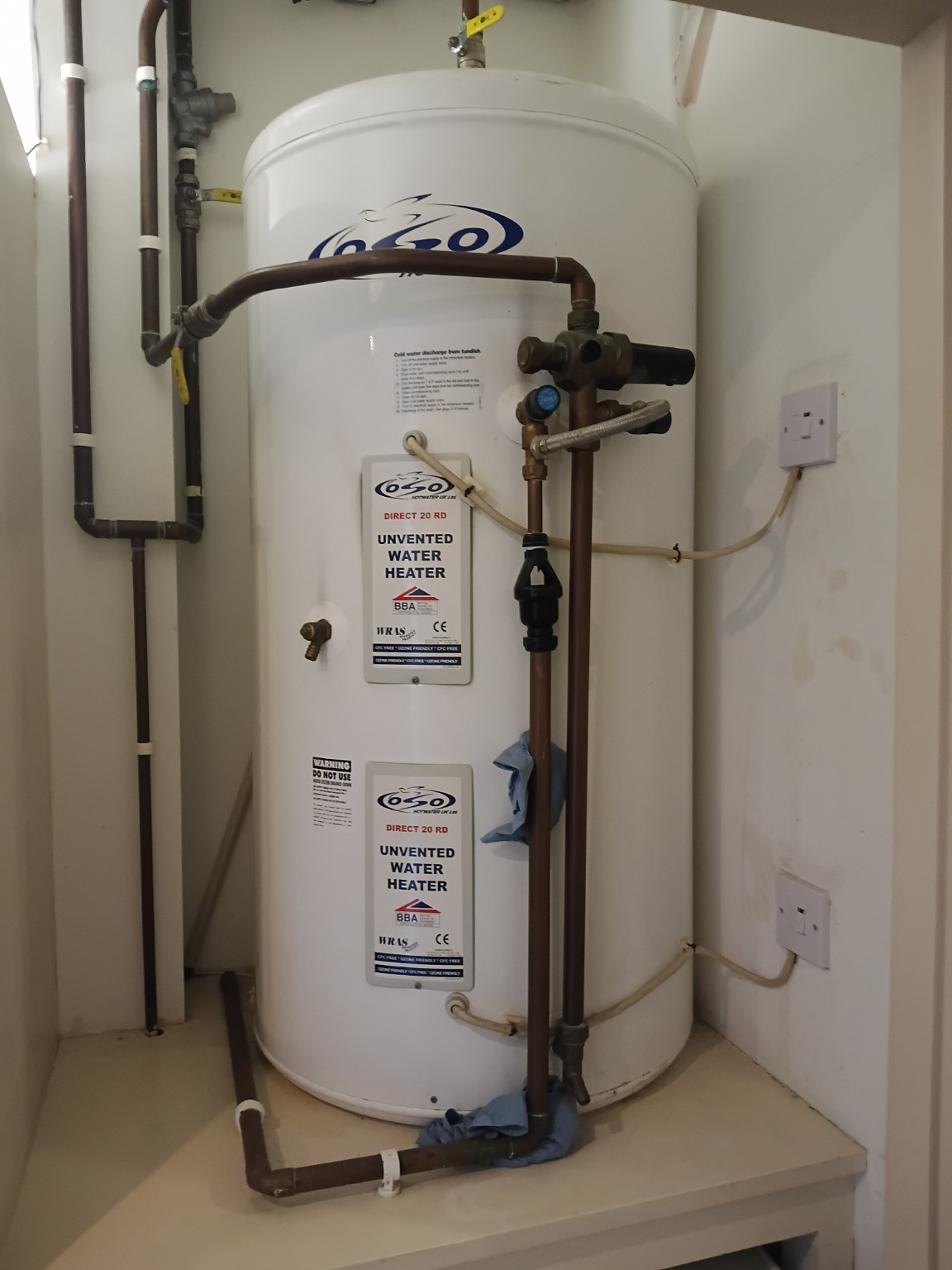
No obvious burn marks
The small fuse drawer holds a cartridge fuse. An undamaged-looking face does not prove that the terminals or fuse contacts behind it are sound.
Why faults happen, what you can safely observe, and when to stop using the heater. Illustrated with photographs from our own service and repair visits.
Look for a small open-sided fitting in the cylinder’s safety discharge pipe. The opening lets you see water released by a safety valve.
In this photograph, it is the black fitting between the upper and lower copper pipes. It provides an air break; it does not control the cylinder pressure or cure a fault.
During ordinary operation it should not be continually running. Water passing through can be a warning that the expansion system, pressure controls or temperature controls need attention.
Approved Document G, paragraph 3.55 explains discharge visibility at the tundish.
They can look similar. The removable fuse drawer is the important clue on a 13 A fused connection unit.
The small fuse drawer holds a cartridge fuse. An undamaged-looking face does not prove that the terminals or fuse contacts behind it are sound.
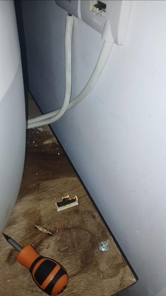
Scorching and melted plastic are signs of damage, not normal wear. Damage may be hidden inside the drawer before it is obvious on the faceplate. Do not pull out the fuse holder to inspect it yourself.
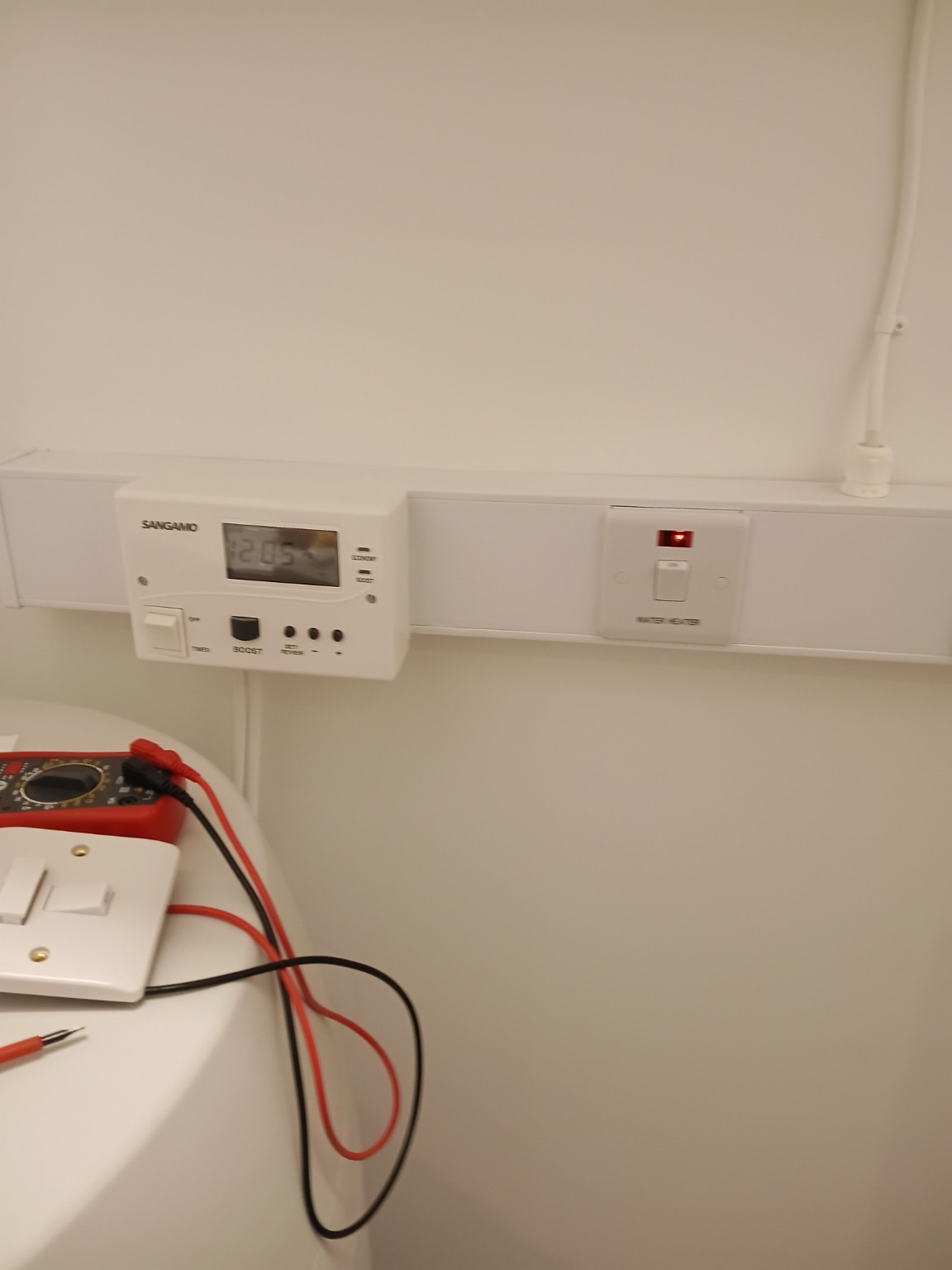
This type isolates live and neutral together. Circuit protection is provided elsewhere. The faceplate alone cannot establish whether the full installation is safe.
A 3 kW element rated at 240 V draws about 12.5 A at that voltage, often for a prolonged heating period. A loose connection, worn contact or poor contact at the fuse can create local resistance and heat. Replacing a fuse alone will not repair damaged contacts or wiring.
A 13 A fused spur is not suitable where the cylinder manufacturer specifies a minimum 20 A double-pole isolator. For example, the OSO SX iQ manual specifies that arrangement. If your cylinder has fused spurs, have the exact model’s instructions and the electrical installation checked.
This is not a claim that every 13 A fused connection unit is unsuitable for every water heater. Suitability depends on the appliance instructions and circuit design. Equally, fitting a 20 A switch does not upgrade the rating of the cable, programmer or protective device.
If you already have the unfused “Water Heater” type: include it in servicing checks too. Its rating, connections, cable, circuit protection and condition must be verified. Never replace a fused spur with an unfused switch as a DIY shortcut.
OSO SX iQ manual, electrical installation, page 11 · Example 20 A water-heater switch specification
One symptom can have several causes. These observations help an engineer investigate; they do not confirm a diagnosis.
Water expands as it heats. An external expansion vessel, or an internal air space on some cylinders, provides room for that expansion. If this provision is lost, pressure can rise until a relief valve opens.
A valve that does not reseat properly, or an inlet pressure-control fault, can also cause discharge. The tundish shows the symptom; it is not necessarily the faulty part.
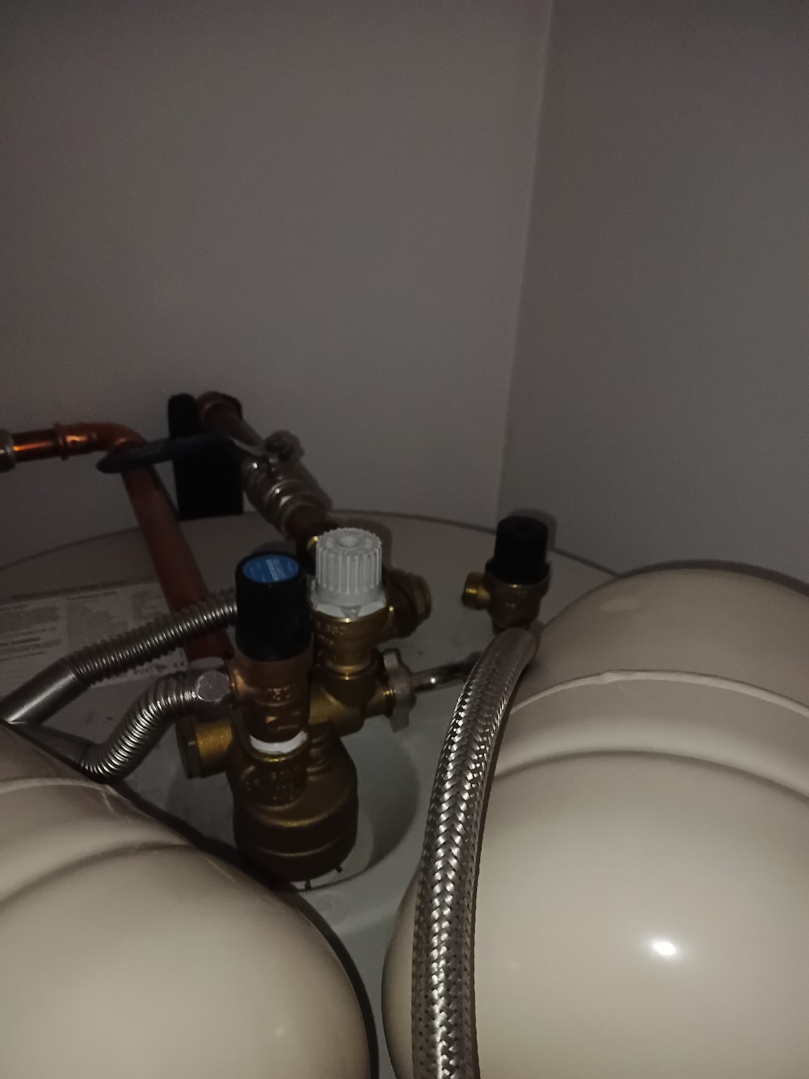
Does it drip only while heating, continuously, or after taps close? Note the pattern from a safe distance. Do not touch discharge water to check its temperature.
The cylinder may not have received its scheduled heating supply. A timer with the wrong time, an off-peak supply issue, a failed element or thermostat can all leave the water cold.
If the upper boost heater works but the lower heater does not, only the upper part of the cylinder may be heated. The result can be a small amount of hot water that quickly runs out.
Read the programmer clock, heating schedule and any visible error message. Check your electricity tariff and expected heating period. Tell the engineer whether boost still works and when hot water last worked normally.
Heat can build at a poor terminal or fuse contact while the immersion carries its heating current. Melting, a brown patch or a hot-plastic smell can indicate developing damage.
A damaged spur may stop supplying the heater, so an apparent “no hot water” fault can originate at the switch rather than the cylinder.
Your unvented cylinder relies on the incoming mains supply. A restriction at the inlet valve or strainer, pressure-control trouble, or demand from several outlets can reduce flow. A sudden stop in moving water can produce a pressure surge known as water hammer.
Is the problem at every hot tap, or only one shower? Are cold taps also affected? If just one shower is weak while other outlets work normally, its cartridge, hose or local filter may need investigation.
A valve joint, immersion seal or pipe connection can leak without the cylinder shell itself having failed. Repeated dampness and deposits around a fitting can help identify a slow leak. Water can also travel along pipework, so the wettest spot is not always the source.
Photograph the first visible wet area, nearby joints and the wider cupboard. Note whether it appears during heating, after water use or all the time. Keep stored belongings clear of the affected area.
A circuit breaker, RCD and thermal cut-out perform different jobs. Electrical trips may involve a damaged element, moisture, wiring faults or excessive demand. A thermal cut-out responds to excessive temperature or a control fault.
The cause needs investigation before the heater is put back into normal service. Repeatedly restoring power can conceal a fault without fixing it.
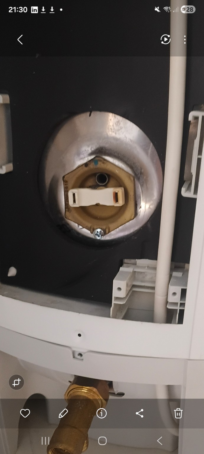
The lower immersion usually heats the main stored volume. An upper immersion commonly supplies a smaller top-up when the main heating period has not provided enough hot water. Your cylinder and wiring may differ, so identify your controls before changing settings.
Leaving boost selected can make it reheat whenever its thermostat calls, potentially at your daytime rate. With some controllers, continuous mode heats the main element instead. Check the controller model rather than assuming what its label means.
If you have a time-of-use tariff, check its actual cheap-rate hours and the programmer’s clock, including changes after a power cut or clock change. A suitable controller can schedule main heating and limit boost duration.
Two elements rated at 3 kW each can create about twice the instantaneous demand of one. A shared switch, controller or cable may not be designed for that load.
These figures illustrate rated demand, not the cost of a full heating cycle. Until the manufacturer’s instructions and circuit design have been verified, avoid running both together. Correctly designed systems may permit it; the arrangement must be checked.
A service should leave you knowing where your tundish is, how your heating controls work, what expansion provision your cylinder uses, and which defects need attention. Keep the service record with your cylinder instructions.
Valve operation, visible discharge and the accessible discharge route should be checked against the installation requirements.
The engineer checks the expansion arrangement, leaks and component condition. Vessel pressures and air-pocket procedures are model-specific; one setting does not suit every cylinder.
Heating schedules, boost operation and accessible electrical components deserve attention, with findings recorded and any required electrical testing identified.
The cylinder label, a wide view of the cupboard, tundish, switch fronts, programmer display and the visible fault. Keep covers closed and stand clear of hot discharge or damaged electrics.
Send photos on WhatsAppCall 07549 813 159Use the manual for your exact cylinder model and production year. This guide explains symptoms; repairs, electrical alterations and safety-valve work require competent people.
Photographs are from Manchester Pipe and Site Services’ own work. Close-up views help identify components; they are not certificates of the installation’s condition.